Precision-engineered fine-pitch modules, high-load interactive surfaces, and ultra-high refresh visual systems optimized for continuous 24/7/365 operations.
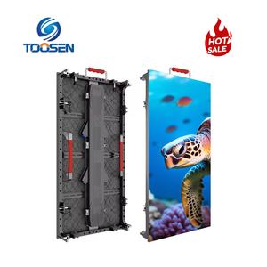
A comprehensive examination of optical physics, mechanical tolerances, and ergonomic compliance in modern control room display infrastructure.
Unlike entertainment stages or digital-out-of-home billboards, control room LED walls operate within rigorous ergonomic constraints defined by ISO 11064 (Ergonomic design of control centres).
Continuous monitoring by console operators requires pixel pitches spanning P0.7 to P1.56mm, calibrated to a non-fatiguing luminance threshold between 100 and 350 nits, paired with ultra-deep black surface coatings to minimize specular reflections.
Thermal accumulation is the primary driver of catastrophic LED diode degradation and chromatic drift over time. Critical mission deployments require fanless, extruded or die-cast aluminum heat-dissipating chassis.
By engineering native thermal pathways directly from the driver ICs to the rear structural housing, cabinet surface operating temperatures remain below 38°C, sustaining diode half-life past 100,000 operational hours.
Single points of failure are unacceptable in security operations centers (SOC), emergency dispatch facilities, and electrical grid monitoring hubs.
Premier Chinese exporters integrate dual hot-swappable switch-mode power supplies (SMPS) wired in N+1 or 2N failover loops, combined with dual receiving cards parsing mirrored gigabit Ethernet and fiber optic signals to ensure zero operational blackouts.
Evaluating pixel surface integrity, impact vulnerability, contrast ratio, and blue light thermal dissipation across dominant manufacturing topologies.
| Evaluation Parameter | Surface Mount Device (SMD) | Integrated Matrix Device (IMD 4-in-1) | Full Flip-Chip COB (Chip-on-Board) |
|---|---|---|---|
| Typical Pixel Pitch (mm) | 1.25mm – 3.91mm | 0.93mm – 1.56mm | 0.4mm – 1.25mm |
| Encapsulation Protection | Exposed solder legs; susceptible to shear impact | Reinforced 4-pixel resin cluster | Continuous epoxy/silicone nano-coating (IP65 front) |
| Surface Hardness & Durability | 2H rating (Vulnerable to cleaning abrasion) | 3H rating | 4H to 6H rating (Anti-collision, anti-static, dust-proof) |
| Contrast Ratio (Ambient Light) | 3,000:1 – 5,000:1 | 6,000:1 – 8,000:1 | 10,000:1 – 25,000:1 (Ultra-black optical matrix) |
| Thermal Resistance (Rth j-s) | High (Heat traverses through lead frames) | Moderate | Extremely Low (Direct die-to-substrate bonding) |
| Blue Light Emission / Eye Strain | Standard peak emission at 450nm | Slightly reduced by diffusion lens | TÜV Rheinland certified low blue light surface treatment |
Macro-level technological vectors redefining how system integrators, AV consultants, and military contractors source Chinese LED hardware.
As advanced transfer techniques and automated optical inspection (AOI) mature in Shenzhen and Guangdong manufacturing corridors, production yields for P0.625mm and P0.78mm modules have risen sharply.
This efficiency drops cost per square meter, enabling regional transport hubs and defense agencies to deploy native 8K/16K canvases without front-surface optical stitching seams.
Legacy control rooms required bulky external multi-window matrix switchers, converting signals through multiple HDMI/DVI hops. Procurement guidelines increasingly mandate integrated SDVoE / SMPTE ST 2110 receiver blades residing directly inside the LED video wall controller.
This architecture yields uncompressed, sub-frame latency (<100 microseconds) visual telemetry from distributed field encoders.
With global mandates prioritizing ESG compliance, enterprise procurement focuses heavily on parasitic energy loss. Advanced power management units—such as dynamic common-cathode silicon and patented power management tools—actively cycle non-illuminated pixels into micro-watt states.
This cuts heat loads inside closed command bunkers by up to 35%, slashing HVAC electrical demand.
Stringent manufacturing governance, state-of-the-art cleanroom lines, and verifiable Factory Acceptance Testing (FAT).
Strict design governance ensures complete electromagnetic compatibility compliance, encompassing CE-EMC (EN55032 Class B for residential/commercial infrastructure), FCC Part 15 Class A/B, UL62368-1, and RoHS compliance across all assemblies.
Ultra-fine pitch COB displays are manufactured within automated SMT environments maintaining ISO 7 (Class 10,000) air purity, eliminating micro-particulate contamination during silicon die wire bonding and resin deposition.
Prior to sea/air dispatch, complete display canvases undergo white-balance burn-in, thermal chamber cycling (-20°C to +55°C), high-vibration transit simulation, and full Factory Acceptance Testing signed off by dedicated quality engineers.
Long-term lifecycle assurance is maintained through centralized component stockpiling, batch-matched diode binning, and regional service hubs capable of rapid module turnaround and micro-soldering repairs.
Technical clarity for AV systems consultants, procurement directors, and command center infrastructure architects.
Optimal pixel pitch calculation relies on the human eye’s visual acuity limit (1 arcminute of resolution, or 20/20 vision). The industry benchmark formula for resolving zero visible pixelation is: Optimal Viewing Distance (Meters) = Pixel Pitch (mm) × 1.0 to 1.5. In a typical command center where console operators sit 2.5 meters from the visual display, a pixel pitch between P1.25mm and P1.56mm guarantees continuous image cohesion. For critical front-row supervisory desks situated within 1.5 meters, sub-millimeter pitches such as P0.93mm or P0.78mm MicroLED are required to prevent visual fatigue and pixelation during text-dense SCADA or geospatial surveillance analysis.
In traditional common anode LED driver configurations, a uniform 5V power supply feeds the Red, Green, and Blue diodes simultaneously. However, Red diodes inherently require only ~2.1V to 2.4V forward voltage, while Green and Blue require ~3.0V to 3.2V. The excess voltage supplied to the Red diode in common anode systems is dissipated purely as wasted thermal energy. Common cathode systems utilize split-rail electrical feeds (e.g., dedicated 2.8V for Red, 3.8V for Green/Blue). This engineering separation directly reduces total cabinet operating power consumption by 20% to 35%, drops cabinet operational surface temperatures by 8°C to 12°C, and prevents chromatic yellowing over extended lifespans.
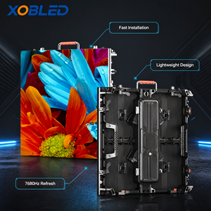
Control rooms increasingly double as crisis briefing centers where broadcast cameras, mobile recording, and video conferencing feeds operate simultaneously. Moiré interference occurs when the pixel array of the LED video wall overlaps geometrically with the camera sensor's Bayer filter grid. Premium Chinese manufacturers mitigate this via three engineering vectors: applying micro-etched matte anti-glare (AG) surface diffusion layers, utilizing optical black-masking resins with gloss levels under 5 GU (Gloss Units), and selecting specialized high-frequency PWM driver ICs that achieve 7,680Hz refresh rates with 16-bit grayscale depth at ultra-low brightness levels.
Thermal planning requires translating display wattage into British Thermal Units (BTU). As a standard rule: BTU/hr = Max Display Operating Watts × 3.412. For an average 600-nit, 30-square-meter P1.25mm video wall consuming approximately 180W/m² in sustained operation, the display will dissipate roughly 18,400 BTU/hr of thermal energy into the control room envelope. Structural walls must be fabricated to load-bearing tolerances sustaining 28kg to 45kg per square meter (inclusive of internal structural unistrut framework), and HVAC ducting must route laminar airflow across the rear chassis void, maintaining ambient intake temperatures between 18°C and 22°C.
Factory-calibrated uniformity across brightness and chromaticity (CIE 1931 coordinate space) can be ruined if mechanical alignment pins shift or if cabinets deform under shock. Premier exporters house fine-pitch panels in shock-isolated, anti-static flight cases or custom maritime wooden crates lined with high-density EVA foam. Each cabinet frame is CNC-machined to dimensional tolerances within ±0.02mm, utilizing industrial neodymium guide pins and precision edge-latches. Furthermore, flash calibration chips reside natively on each individual LED module hub card; if a module is swapped during service, it automatically retrieves its factory calibration coefficients from the receiving card, preserving uniformity without on-site re-calibration.
Connect directly with our engineering division for pixel pitch evaluations, optical lux simulations, heat-load dissipation calculations, and competitive OEM/ODM export proposals.
Get a Quote